


Volkswagen ID.3: Electric drive. High-voltage battery unit, edge of upper part of battery housing without wax
- Assembly overview – high-voltage battery, installed
- Assembly overview – high-voltage battery, installed
- Inspecting and classifying high-voltage battery 1 AX2
- Diagnosis of high-voltage battery 1 [AX2]
- Checking high-voltage battery for leaks
- Leakage test of high-voltage battery 1 [AX2]
- Removing and installing high-voltage battery 1 [AX2]
- Removing and installing high-voltage battery 1 [AX2]
- Raising high-voltage battery 1 [AX2]
- Opening high-voltage battery 1 AX2
- Closing high-voltage battery 1 AX2
- Closing high-voltage battery 1 AX2
- Voltage and insulation measurement
- Voltage and insulation measurement
- Interrupting electrical circuit
- Opening electrical circuit
- Interrupting electrical circuit
- Removing and installing battery regulation control unit J840
- Charging and discharging battery modules
- Checking whether upper part of battery housing can be reused
- Renewing lower part of battery housing
- Renewing high-voltage battery 1 [AX2]
Assembly overview – high-voltage battery, installed
Assembly overview – high-voltage battery, installed
.webp)
1 - High-voltage battery 1 -AX2-
❏ → Rep. gr.93; Removing and installing high-voltage battery 1 [AX2]
2 - Bolt
❏ Qty. 16
❏ Renew after removing
❏ Specified torque and tightening sequence → Fig.
3 - Skid plate for high-voltage battery
❏ → General body repairs, exterior; Rep. gr.66; Underbody cladding; Removing and installing high-voltage battery skid plate
4 - Reinforcement for high-voltage battery body aperture
5 - Centre underbody cladding
❏ → General body repairs, exterior; Rep. gr.66; Underbody cladding; Removing and installing centre underbody cladding
6 - Bolt
❏ Qty. 14
❏ Renew after removing
❏ Specified torque and tightening sequence → Fig.
7 - Bolt
❏ Qty. 4
❏ Renew after removing
❏ Specified torque and tightening sequence → Fig.
8 - Banjo bolt
❏ Qty. 4
❏ Renew after removing
❏ 150 Nm
High-voltage battery – specified torque and tightening sequence
.webp) StageBoltsSpecified torque/turning further angle1-1- to -30-50 Nm +90°2-31- to -34-40 Nm +180°
StageBoltsSpecified torque/turning further angle1-1- to -30-50 Nm +90°2-31- to -34-40 Nm +180°
Assembly overview – high-voltage battery, installed
Assembly overview – high-voltage battery, installed
.webp)
1 - High-voltage battery 1 -AX2-
❏ → Rep. gr.93; Removing and installing high-voltage battery 1 [AX2]
2 - Bolt
❏ Qty. 24
❏ Renew after removing
❏ Specified torque and tightening sequence → Fig.
3 - Skid plate for high-voltage battery
❏ → General body repairs, exterior; Rep. gr.66; Underbody cladding; Removing and installing high-voltage battery skid plate
4 - Bolt
❏ Qty. 4
❏ Renew after removing
❏ Specified torque and tightening sequence → Fig.
5 - Banjo bolt
❏ Qty. 4
❏ Renew after removing
❏ 150 Nm
High-voltage battery – specified torque and tightening sequence
.webp) StageBoltsSpecified torque/turning further angle1-1- to -24-50 Nm +90°2-25- to -28-40 Nm +180°
StageBoltsSpecified torque/turning further angle1-1- to -24-50 Nm +90°2-25- to -28-40 Nm +180°
Inspecting and classifying high-voltage battery 1 AX2
Inspecting and classifying high-voltage battery 1 AX2
Special tools and workshop equipment required
♦ diagnosis box -VAS 5581A-
♦ diagnostic cable -VAS 5581A/11-
♦ vehicle diagnostic tester
.webp) CAUTION
CAUTION
The high-voltage battery can become extremely hot. This can cause injuries.
Take care not to burn your hands.
– Put on protective gloves.
Note
Inform the high-voltage expert if any problems arise or entries in the event memory appear.
Visual inspection of high-voltage battery 1 [AX2]
Inspect the high-voltage battery 1 -AX2- for the following:
– Cracks in upper or lower parts of battery housing
– Deformations in upper or lower parts of battery housing
– Colour changes due to temperature impact and tarnishing of battery housing
– Escaping electrolyte
– Damage to high-voltage contacts
– Legible information and warning stickers properly in place
– Fitted potential equalisation line
– Corrosion damage
– If abnormalities are detected during the visual inspection, a classification of the high-voltage battery 1 -AX2- must be carries out.
Preparatory work on removed high-voltage battery:
– Connect diagnosis box -VAS 5581A- via diagnostic cable -VAS 5581A/11- to vehicle diagnostic tester.
Important
● Before commencing the diagnosis, Gateway (GW) operating mode must be selected on the diagnosis box -VAS 5581A- .
– Connect diagnostic cable -VAS 5581A/11- to 12V-connector -1- of high-voltage battery 1 -AX2-.
– Connect black earth terminal of diagnostic cable -VAS 5581A/11- to earth of battery housing -arrow-.
.webp)
Classification of high-voltage battery:
– Carry out classification of high-voltage battery using → Vehicle diagnostic tester → Rep. gr.00; Access to diagnoses.
Diagnosis of high-voltage battery 1 [AX2]
Diagnosis of high-voltage battery 1 [AX2]
Special tools and workshop equipment required
♦ diagnosis box -VAS 5581A-
♦ diagnostic cable -VAS 5581A/11-
♦ vehicle diagnostic tester
High-voltage battery installed
Important
● The high-voltage battery 1 remains installed in the vehicle during the diagnosis.
– Carry out diagnosis of high-voltage battery using → Vehicle diagnostic tester → Rep. gr.00; Access to diagnosis.
High-voltage battery removed
– Connect diagnosis box -VAS 5581A- via diagnostic cable -VAS 5581A/11- to vehicle diagnostic tester.
Important
● Before commencing the diagnosis, Gateway (GW) operating mode must be selected on the diagnosis box -VAS 5581A- .
– Connect diagnostic cable -VAS 5581A/11- to 12V-connector -1- of high-voltage battery 1 -AX2-.
– Connect black earth terminal of diagnostic cable -VAS 5581A/11- to earth of battery housing -arrow-.
– Carry out diagnosis of high-voltage battery using → Vehicle diagnostic tester → Rep. gr.00; Access to diagnosis.
.webp)
For further measures on high-voltage battery:
– Disconnect diagnosis box -VAS 5581A-.
Checking high-voltage battery for leaks
Checking high-voltage battery for leaks
Special tools and workshop equipment required
♦ pressure and vacuum pump -VAS 671 005-
♦ sealing plugs -T10607-
Note
Searching for leaks from the high-voltage battery 1 -AX2- is only required if the leak test under pressure failed.
Note
Leaks are indicated by bubbles.
Note
Leaks can potentially be traced to the banjo bolts on the underside of high-voltage battery 1 -AX2-.
– Seal connections of high-voltage battery 1 -AX2- using sealing plugs -T10607-.
– Build up pressure using pressure and vacuum pump -VAS 671 005-.
– Using commercially available leak detection spray
♦ Spray contact surfaces of upper part of battery housing and lower part of battery housing.
♦ Spray banjo bolts on underside
Leakage test of high-voltage battery 1 [AX2]
Leakage test of high-voltage battery 1 [AX2]
Special tools and workshop equipment required
♦ Distributor -VAS 691 005/1-
♦ Pressure and vacuum pump -VAS 671 005-
♦ Pressure sensor -V.A.G 1397B-
♦ Pressure sensor -VAS 611 013-
♦ Sealing plug -T10607-
♦ Test connector set -VAS 6911/3B-
Important
● A leak test must always be carried out with vacuum before removing and after installing the high-voltage battery 1 -AX2-.
● High-voltage battery 1 -AX2- is acclimatised.
● The leakage test and acclimatisation must be carried out at a steady ambient temperature.
– Check that gasket -arrows- is correctly seated.
– Check connector strip for moisture. Carefully wipe with lint-free cleaning cloth.
.webp)
– Carry out “Leak test” function with → Vehicle diagnostic tester → Rep. gr.00; Access to diagnoses.
Removing and installing high-voltage battery 1 [AX2]
Removing and installing high-voltage battery 1 [AX2]
Special tools and workshop equipment required
♦ drip tray -VAS 6208-
♦ engine bung set -VAS 6122-
♦ hose clamps, up to 25 mm -3094-
♦ insulating mat -VAS 6762/44-
♦ scissor-type assembly platform -VAS 6131B-
.webp) DANGER
DANGER
High voltage can cause fatal injury.
Danger of severe or fatal injuries from electric shock or electric arcs.
– Have a high-voltage technician (HVT) or a high-voltage expert (HVE) de-energise the high-voltage system.
.webp) CAUTION
CAUTION
The high-voltage battery can become extremely hot. This can cause injuries.
Take care not to burn your hands.
– Put on protective gloves.
.webp) NOTICE
NOTICE
Potential damage to vehicle
– Make sure that nobody is inside the vehicle after the high-voltage battery has been removed.
The high-voltage battery 1 -AX2- will subsequently be referred to as “high-voltage battery”.
Removing
– → Rep. gr.93; Visual inspection of high-voltage battery 1 [AX2].
NOTICE
Potential damage to vehicle from slipping.
– The dimensions of the vehicle support plates and their spindles must be sufficient to ensure that the load that is imparted centrally between the outer edge and centre of the vehicle support plates can be supported. If the dimensions are not sufficient, different vehicle support plates must be used that meet this requirement.
Note
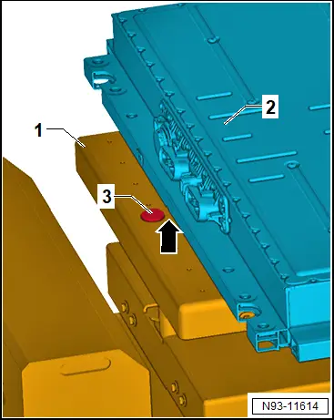
Not every lifting platform is suitable for the removal of the high-voltage battery. Ensure that there is sufficient clearance. When lifting, ensure that there is sufficient clearance -a- around the high-voltage battery so that it can be placed on the scissor-type assembly platform -VAS 6131B-.
– Swivel lifting platform arm with vehicle support plate -1- up to frame of high-voltage battery -2-. Then swivel back lifting platform arm with vehicle support plate -1- far enough -a- to allow for lowering high-voltage battery -2- in the following step.
.webp)
– Remove front underbody cladding → General body repairs, exterior; Rep. gr.66; Underbody cladding; Removing and installing front underbody cladding.
– Detach front right wheel housing liners in area of threaded connection of high-voltage battery → General body repairs, exterior; Rep. gr.66; Wheel housing liner; Removing and installing front wheel housing liner.
– Remove side underbody cladding → General body repairs, exterior; Rep. gr.66; Underbody cladding; Removing and installing side underbody cladding.
– Remove centre underbody cladding.
– Remove rear centre underbody cladding → General body repairs, exterior; Rep. gr.66; Underbody cladding; Removing and installing rear centre underbody cladding.
– Remove rear underbody cladding → General body repairs, exterior; Rep. gr.66; Underbody cladding; Removing and installing rear underbody cladding.
– Loosen and unscrew bolts -2- by hand.
– Pull out reinforcement for high-voltage battery body aperture -1-.
– → Rep. gr.93; De-energising high-voltage system
.webp)
– Unscrew nut for potential equalisation line -1-. Counterhold on centre hex stud, when doing this.
– Disconnect electrical connector of high-voltage battery -2-.
– Disconnect electrical connector for auxiliary consumers -5- → Rep. gr.93; Disconnecting high-voltage connectors.
– Remove pressure relief valve -3-.
.webp)
– Perform → Rep. gr.93; leakage test of high-voltage battery 1 [AX2].
– Disconnect high-voltage system connection -4- → Rep. gr.93; Disconnecting high-voltage connectors.
– Disconnect DC charging connection -6-.
– Check that gasket -arrows- is correctly seated.
– Check connector strip for moisture, and carefully wipe it dry with a lint-free cloth.
.webp)
– Fit cap -2- on connector strip -1-.
.webp)
– Unscrew bolts -1- from coolant pump for high-voltage battery -V590-.
– Open clip -2-.
.webp)
– Pull coolant pump in direction of -arrow-, and disconnect electrical connector -1-.
.webp)
– Loosen bolts -2- and -3- by hand.
– Unscrew bolts -2- and -3- from high-voltage battery -1-.
.webp)
NOTICE
Risk of damage to the high-voltage battery.
– The high-voltage battery must lie flat against the scissor-type assembly platform -VAS 6131B-. Remove any kind of soiling.
Important
● Scissor-type assembly platform and front side of high-voltage battery must be flush -arrow-.
– Lay insulating mat -VAS 6762/44--2- centrally on scissor-type assembly platform -VAS 6131B--3-.
.webp)
– Align scissor-type assembly platform -VAS 6131B--1- so that it is flush with front side of high-voltage battery; high-voltage battery must lie flat against the platform.
.webp)
CAUTION
Risk of injury from moving parts.
Body parts could suffer contusions.
– Never reach or step into the hazard zone.
NOTICE
Risk of damage to components caused by moving scissor-type assembly platform.
– Ensure sufficient clearance to body.
– Ensure sufficient clearance to electrical wiring and electrical connectors.
– Raise scissor-type assembly platform -VAS 6131B- -3- far enough to take up weight of high-voltage battery -1-.
– Loosen and unscrew bolts -2- from high-voltage battery -1- by hand.
.webp)
– Carefully lower high-voltage battery until coolant connections become accessible.
– Place drip tray -VAS 6208- under coolant connections.
– Clamp off coolant hoses -1- and -2- using hose clamps, up to 25 mm -3094- -A-.
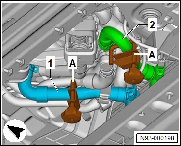
– Pull out retaining clips for coolant connections -1- in direction of -arrow-, and pull coolant hoses off high-voltage battery.
– Seal coolant connections with plugs from engine bung set -VAS 6122-.
.webp)
– Carefully lower high-voltage battery.
– Secure media duct -1- with screws -2- → Electronic parts catalogue (ETKA).
.webp) ComponentSpecified torqueBolt -2- 20 Nm
ComponentSpecified torqueBolt -2- 20 Nm
Installing
Install in reverse order of removal, observing the following:
New high-voltage battery
– Perform procedure for renewal of high-voltage battery → Rep. gr.93; Renewing high-voltage battery 1 [AX2].
All vehicles (continued)
Removed high-voltage battery
– Remove separating film -2- from lower part of battery housing -1-.
– Clean area of separating film -2- with cleaning solution → Electronic parts catalogue (ETKA).
– Renew separating film -2-.
.webp)
All vehicles (continued)
CAUTION
Risk of injury from moving parts.
Body parts could suffer contusions.
– Never reach or step into the hazard zone.
NOTICE
Risk of damage to components caused by moving scissor-type assembly platform.
– Ensure sufficient clearance to body.
– Ensure sufficient clearance to electrical wiring and electrical connectors.
– Align high-voltage battery on scissor-type assembly platform -VAS 6131B- under vehicle.
– Raise high-voltage battery on scissor-type assembly platform -VAS 6131B- to 5 cm before end position.
– Connect coolant hoses.
– Raise high-voltage battery on scissor-type assembly platform -VAS 6131B- to end position.
– Tighten bolts -2- to specified torque according to specified tightening sequence.
– Tighten bolts -2- and -3- to specified torque according to specified tightening sequence.
– Connect high-voltage system connection -4-.
– Connect DC charging connection -6-.
– Perform → Rep. gr.93; leakage test of high-voltage battery 1 [AX2].
– Connect electrical connector of high-voltage battery -2-.
– Connect electrical connector for auxiliary consumers -5-.
– Install pressure relief valve -3-.
– Install body aperture reinforcement for high-voltage battery -1-. To do this, tighten bolts -2- in specified tightening sequence to specified torque.
– Tighten nut for potential equalisation line to specified torque. Counterhold on centre hex stud when doing this.
– → Rep. gr.19; Cooling system/coolant; Filling cooling system
.webp) WARNING
WARNING
High voltage can cause fatal injury.
Danger of severe or fatal injuries from electric shock or electric arcs.
– Have a high-voltage technician (HVT) or a high-voltage expert (HVE) re-energise the high-voltage system.
– → Rep. gr.93; Re-energise high-voltage system.
Tightening torques
♦ → Rep. gr.93; Assembly overview - high-voltage battery (installed)
♦ → Rep. gr.93; Overview of fitting locations - potential equalisation lines
Removing and installing high-voltage battery 1 [AX2]
Removing and installing high-voltage battery 1 [AX2]
Special tools and workshop equipment required
♦ drip tray -VAS 6208-
♦ engine bung set -VAS 6122-
♦ hose clamps, up to 25 mm -3094-
♦ insulating mat -VAS 6762/44-
♦ scissor-type assembly platform -VAS 6131B-
.webp) DANGER
DANGER
High voltage can cause fatal injury.
Danger of severe or fatal injuries from electric shock or electric arcs.
– Have a high-voltage technician (HVT) or a high-voltage expert (HVE) de-energise the high-voltage system.
.webp) CAUTION
CAUTION
The high-voltage battery can become extremely hot. This can cause injuries.
Take care not to burn your hands.
– Put on protective gloves.
.webp) NOTICE
NOTICE
Potential damage to vehicle
– Make sure that nobody is inside the vehicle after the high-voltage battery has been removed.
The high-voltage battery 1 -AX2- will subsequently be referred to as “high-voltage battery”.
Removing
– → Rep. gr.93; Visual inspection of high-voltage battery 1 [AX2].
NOTICE
Potential damage to vehicle from slipping.
– The dimensions of the vehicle support plates and their spindles must be sufficient to ensure that the load that is imparted centrally between the outer edge and centre of the vehicle support plates can be supported. If the dimensions are not sufficient, different vehicle support plates must be used that meet this requirement.
Note
Not every lifting platform is suitable for the removal of the high-voltage battery. Ensure that there is sufficient clearance. When lifting, ensure that there is sufficient clearance -a- around the high-voltage battery so that the high-voltage battery can be placed on the scissor-type assembly platform -VAS 6131B-.
– Swivel lifting platform arm with vehicle support plate -1- up to frame of high-voltage battery -2-. Then swivel back lifting platform arm with vehicle support plate -1- far enough -a- to allow for lowering high-voltage battery -2- in the following step.
.webp)
– Remove front underbody cladding → General body repairs, exterior; Rep. gr.66; Underbody cladding; Removing and installing front underbody cladding.
– Detach front right wheel housing liners in area of threaded connection of high-voltage battery → General body repairs, exterior; Rep. gr.66; Wheel housing liner; Removing and installing front wheel housing liner.
– Remove side underbody cladding → General body repairs, exterior; Rep. gr.66; Underbody cladding; Removing and installing side underbody cladding.
– Remove rear centre underbody cladding → General body repairs, exterior; Rep. gr.66; Underbody cladding; Removing and installing rear centre underbody cladding.
– Remove rear underbody cladding → General body repairs, exterior; Rep. gr.66; Underbody cladding; Removing and installing rear underbody cladding.
– → Rep. gr.93; De-energise high-voltage system.
NOTICE
Potential leakage of the high-voltage battery due to impurities in the seal area of the electrical plug connectors.
– Sealing surfaces on the connector strip must be free of impurities.
– Remove coarse soiling in area of electrical connectors.
– Unscrew nut for potential equalisation line -1-. Counterhold on centre hex stud, when doing this.
– Disconnect electrical connector of high-voltage battery -2-.
– Disconnect electrical connector for auxiliary consumers -5- → Rep. gr.93; Disconnecting high-voltage connectors.
– Remove pressure relief valve -3-.
.webp)
– Perform → Rep. gr.93; leakage test of high-voltage battery 1 [AX2].
Note
For better disconnection of the high-voltage system connector, the guide of the high-voltage system connection cable must be removed.
– Unclip locking devices -arrow-.
– Separate lower part of cable duct -1- from cable duct cover -2-.
.webp)
– Disconnect high-voltage system connection -4- → Rep. gr.93; Disconnecting high-voltage connectors.
– Disconnect DC charging connection -6-.
– Check that gasket -arrows- is correctly seated.
– Carefully absorb moisture from connector strip using lint-free cleaning cloth.
NOTICE
Potential leakage of the high-voltage battery due to impurities in the seal area of the electrical plug connectors.
– Sealing surfaces on the connector strip must be free of impurities.
– Remove soiling from connector strip using lint-free cleaning cloth and cleaning solution → Electronic parts catalogue (ETKA).
.webp)
– Fit cap -2- on connector strip -1-.
.webp)
– Unscrew bolts -1- from coolant pump for high-voltage battery -V590-.
– Open clip -2-.
.webp)
– Pull coolant pump in direction of -arrow-, and disconnect electrical connector -1-.
.webp)
– Loosen bolts -2- and -3- by hand.
– Unscrew bolts -2- and -3- from high-voltage battery -1-.
.webp)
NOTICE
Risk of damage to the high-voltage battery.
– The high-voltage battery must lie flat against the scissor-type assembly platform -VAS 6131B-. Remove any kind of soiling.
– Note position of the spirit level -3- on the scissor-type assembly platform -VAS 6131B-.
– Lay insulating mat -VAS 6762/44- centrally on scissor-type assembly platform -VAS 6131B- -1-.
– Place scissor-type assembly platform -VAS 6131B- -1- underneath, and align it so that high-voltage battery -2- can lie flat against it.
CAUTION
Risk of injury from moving parts.
Body parts could suffer contusions.
– Never reach or step into the hazard zone.
NOTICE
Risk of damage to components caused by moving scissor-type assembly platform.
– Ensure sufficient clearance to body.
– Ensure sufficient clearance to electrical wiring and electrical connectors.
– Raise scissor-type assembly platform -VAS 6131B- -1- far enough to take weight off high-voltage battery.
.webp)
– Loosen and unscrew bolts -2- from high-voltage battery -1- by hand.
.webp)
– Carefully lower high-voltage battery until coolant connections become accessible.
– Place drip tray -VAS 6208- under coolant connections.
– Clamp off coolant hoses -1- and -2- using hose clamps, up to 25 mm -3094- -A-.
.webp)
– Pull out retaining clips for coolant connections -1- in direction of -arrow-, and pull coolant hoses off high-voltage battery.
– Seal coolant connections with plugs from engine bung set -VAS 6122-.
.webp)
– Carefully lower high-voltage battery.
– Secure media duct -1- with screws -2- → Electronic parts catalogue (ETKA).
.webp) ComponentSpecified torqueBolt -2- 20 Nm
ComponentSpecified torqueBolt -2- 20 Nm
Installing
Install in reverse order of removal, observing the following:
New high-voltage battery:
– Perform procedure for renewal of high-voltage battery → Rep. gr.93; Renewing high-voltage battery 1 [AX2].
All vehicles (continued)
Removed high-voltage battery
– Remove separating film -2- from lower part of battery housing -1-.
– Clean area of separating film -2- with cleaning solution → Electronic parts catalogue (ETKA).
– Renew separating film -2-.
.webp)
All vehicles (continued)
CAUTION
Risk of injury from moving parts.
Body parts could suffer contusions.
– Never reach or step into the hazard zone.
NOTICE
Risk of damage to components caused by moving scissor-type assembly platform.
– Ensure sufficient clearance to body.
– Ensure sufficient clearance to electrical wiring and electrical connectors.
– Align high-voltage battery on scissor-type assembly platform -VAS 6131B- under vehicle.
– Raise high-voltage battery on scissor-type assembly platform -VAS 6131B- to 5 cm before end position.
– Connect coolant hoses.
– Raise high-voltage battery on scissor-type assembly platform -VAS 6131B- to end position.
– Tighten bolts -2- to specified torque according to specified tightening sequence.
.webp)
– Tighten bolts -2- and -3- to specified torque according to specified tightening sequence.
– Connect high-voltage system connection -4-.
– Connect DC charging connection -6-.
– Perform → Rep. gr.93; leakage test of high-voltage battery 1 [AX2].
– Connect electrical connector of high-voltage battery -2-.
– Connect electrical connector for auxiliary consumers -5-.
– Install pressure relief valve -3-.
– Tighten nut for potential equalisation line to specified torque, counterholding at centre hex stud while doing so.
– → Rep. gr.19; Cooling system/coolant; Filling cooling system
.webp) WARNING
WARNING
High voltage can cause fatal injury.
Danger of severe or fatal injuries from electric shock or electric arcs.
– Have a high-voltage technician (HVT) or a high-voltage expert (HVE) re-energise the high-voltage system.
– → Rep. gr.93; Re-energise high-voltage system.
Tightening torques
♦ → Rep. gr.93; Assembly overview - high-voltage battery (installed)
♦ → Rep. gr.93; Overview of fitting locations - potential equalisation lines
Raising high-voltage battery 1 [AX2]
Raising high-voltage battery 1 [AX2]
Special tools and workshop equipment required
♦ extension for lifting arm/workshop hoist -VAS 6101-
♦ lifting aid -T10616-
♦ master link -VAS 501 013-
♦ retaining strap -T40155A-
♦ shackle -VAS 691 009A-
♦ workshop hoist -VAS 6100-
Preparing for lifting
The high-voltage battery 1 -AX2- will subsequently be referred to as “high-voltage battery”.
Preparing for lifting, 55 and 62 kWh
– Use mounting points -2-.
.webp)
All vehicles (continued)
Preparing for lifting, 82 kWh
– Use mounting points -2-.
.webp)
All vehicles (continued)
Lifting
– Align extension for lifting arm/workshop hoist -VAS 6101- -A- at marking -arrow- and secure to workshop hoist -VAS 6100- -B-.
– Position workshop hoist -VAS 6100- -A- and workshop hoist -VAS 6100- -B- centrally above high-voltage battery -1-.
– Secure retaining strap -T40155A- -F- with shackle -VAS 691 009A- -H- to master link -VAS 501 013- -G-.
– Tighten lifting aid -T10616- -E- at mounting points of high-voltage battery -1- to specified torque.
– Attach mounting bracket -T10616- -E- with shackle -VAS 691 009A- -D- to retaining strap -T40155A- -F-.
.webp) CAUTION
CAUTION
Risk of injury from moving parts.
Body parts could suffer contusions.
– Never reach or step into the hazard zone.
– Lift high-voltage battery -1-.
.webp)
Tightening torques
BoltsSpecified torque Bolts for lifting aid -T10616-50 Nm
Opening high-voltage battery 1 AX2
Opening high-voltage battery 1 AX2
Special tools and workshop equipment required
♦ nylon pipe brush -VAS 294 029-
Opening
– Remove high-voltage battery 1 -AX2- → Rep. gr.93; Removing and installing high-voltage battery 1 AX2.
– Unscrew connecting element -4-.
– Clean threaded holes -4- using nylon pipe brush -VAS 294 029- and commercially available vacuum cleaner with plastic nozzle.
– Remove bolts -3-.
– Remove bolts -2-.
.webp)
 DANGER
DANGER
High voltage can cause fatal injury.
Danger of severe or fatal injuries from electric shock or electric arcs.
– Suitable personal protective equipment (PPE) must be worn for the following work.
– The following steps require a second suitably qualified person to be present to supervise.
– Outside the danger zone, the second person may assist the high-voltage expert where required to the extent of his/her qualification.
– The personal protective equipment (PPE) must be dry and undamaged.
Put on protective equipment → Electronic parts catalogue (ETKA) before performing the following work steps:
♦ Clothing approved for working with electric arcs (minimum protection class 2, at least 318 kJ)
♦ Helmet with visor approved for working with electric arcs (minimum protection class 2, at least 318 kJ)
♦ Gloves approved for working with electric arcs with nitrile glove liners (minimum protection class 2, at least 318 kJ), minimum insulating effect up to 500 V
♦ Safety shoes with ESD protection
– Detach upper part of battery housing -1-.
– → Rep. gr.93; Voltage and insulation measurement.
– → Rep. gr.93; Check whether upper part of battery housing can be reused.
If further work is being performed on high-voltage battery:
– Interrupt electrical circuit → Rep. gr.93; Interrupting electrical circuit.
– Cover areas of high-voltage battery 1 -AX2- that are not being worked on.
Closing high-voltage battery 1 AX2
Closing high-voltage battery 1 AX2
Special tools and workshop equipment required
♦ Hand-cartridge gun -V.A.G 1628-
♦ High-voltage tool set -VAS 6762-
♦ High-voltage tool set -VAS 6883A-
♦ suction lifter -V.A.G 1344-
Installing
– Close electrical circuit → Rep. gr.93; Opening electrical circuit.
– → Rep. gr.93; Diagnosis of high-voltage battery 1 [AX2].
If high-voltage battery 1 -AX2- is opened, the flow-drill screws must be checked and renewed according to the following table.
– Flow-drill screws
Production versionRepair bolt, stage 1Repair bolt, stage 2Inner thread on lower part of battery housing OKInner thread on lower part of battery housing OK Torque specified for production bolt has not been attained.Inner thread on lower part of battery housing not OK (thread stripped)After opening high-voltage battery 1 -AX2-, the original bolts must be used → Electronic parts catalogue (ETKA). Replace production bolt and use max. quantity of 14 → Electronic parts catalogue (ETKA) Use oversized bolt (new thread will be cut) → Electronic parts catalogue (ETKA)
Continued
.webp) NOTICE
NOTICE
Leakage of high-voltage battery 1 -AX2- possible.
– Flange of lower part of battery housing must be free of grease, sealant residue and contamination.
– Use a commercially available vacuum cleaner with plastic nozzle to clean lower part of battery housing; remove sealing material and soiling.
– Clean flange of lower part of battery housing using lint-free cleaning cloth and cleaning solution → Electronic parts catalogue (ETKA).
– Secure suction lifter -V.A.G 1344- -2- at top of upper part of battery housing -1-.
– Turn upper part of battery housing -1- in direction of -arrow-.
– Place on suitable surface.
.webp)
New upper part of battery housing
– Clean flange of upper part of battery housing using lint-free cleaning cloth and cleaning solution → Electronic parts catalogue (ETKA).
All vehicles (continued)
– Apply sealant -3- → Electronic parts catalogue (ETKA) to upper part of battery housing -1- all around and parallel to gasket -2-.
– Place upper part of battery housing -1- evenly on lower part of battery housing.
.webp)
Installing
Install in reverse order of removal, observing the following:
Tightening torques
♦ → Rep. gr.93; Assembly overview - high-voltage battery (removed)
♦ Seal bolts -1- through -18- with wax → Electronic parts catalogue (ETKA).
.webp)
Closing high-voltage battery 1 AX2
Closing high-voltage battery 1 AX2
Special tools and workshop equipment required
♦ Hand-cartridge gun -V.A.G 1628-
♦ High-voltage tool set -VAS 6762-
♦ High-voltage tool set -VAS 6883A-
♦ suction lifter -V.A.G 1344-
Installing
– Close electrical circuit → Rep. gr.93; Opening electrical circuit.
– → Rep. gr.93; Diagnosis of high-voltage battery 1 [AX2].
If high-voltage battery 1 -AX2- is opened, the flow-drill screws must be checked and renewed according to the following table:
– Flow-drill screws
Production versionRepair bolt, stage 1Repair bolt, stage 2Inner thread on lower part of battery housing OKInner thread on lower part of battery housing OK Torque specified for production bolt has not been attained.Inner thread on lower part of battery housing not OK (thread stripped)After opening high-voltage battery 1 -AX2-, the original bolts must be used → Electronic parts catalogue (ETKA). Replace production bolt and use max. quantity of 14 → Electronic parts catalogue (ETKA) Use oversized bolt (new thread will be cut) → Electronic parts catalogue (ETKA)
Continued
.webp) NOTICE
NOTICE
Leakage of high-voltage battery 1 -AX2- possible.
– Flange of lower part of battery housing must be free of grease, sealant residue and contamination.
– Use a commercially available vacuum cleaner with plastic nozzle to clean lower part of battery housing; remove sealing material and soiling.
– Clean flange of lower part of battery housing using lint-free cleaning cloth and cleaning solution → Electronic parts catalogue (ETKA).
– Secure suction lifter -V.A.G 1344- -2- at top of upper part of battery housing -1-.
– Turn upper part of battery housing -1- in direction of -arrow-.
– Place on suitable surface.
.webp)
New upper part of battery housing
– Clean flange of upper part of battery housing using lint-free cleaning cloth and cleaning solution → Electronic parts catalogue (ETKA).
All vehicles (continued)
– Clean flange of upper part of battery housing -1- using lint-free cleaning cloth and cleaning solution → Electronic parts catalogue (ETKA).
– Apply sealant -3- → Electronic parts catalogue (ETKA) to upper part of battery housing -1- all around and parallel to gasket -2-.
– Place upper part of battery housing -1- evenly on lower part of battery housing.
.webp)
Installing
Install in reverse order of removal, observing the following:
Tightening torques
♦ → Rep. gr.93; Assembly overview - high-voltage battery (removed)
♦ Seal bolts -1- through -26- with wax → Electronic parts catalogue (ETKA).
.webp)
Voltage and insulation measurement
Voltage and insulation measurement
Special tools and workshop equipment required
♦ high-voltage test module -VAS 6558-
♦ high-voltage test module -VAS 6558A-
.webp) DANGER
DANGER
High voltage can cause fatal injury.
Danger of severe or fatal injuries from electric shock or electric arcs.
– Suitable personal protective equipment (PPE) must be worn for the following work.
– The following steps require a second suitably qualified person to be present to supervise.
– Outside the danger zone, the second person may assist the high-voltage expert where required to the extent of his/her qualification.
– The personal protective equipment (PPE) must be dry and undamaged.
Put on the required protective equipment for the subsequent work steps → Electronic parts catalogue (ETKA):
♦ Arc flash resistant clothing (at least APC 2, at least 318 kJ)
♦ Helmet with arc flash resistant visor (at least APC 2, at least 318 kJ)
♦ Arc flash resistant gloves with nitrile glove liners (at least APC 2, at least 318 kJ), insulating up to at least 500 V
♦ Safety shoes with ESD protection
All tests must be performed using high-voltage test module -VAS 6558A-/high-voltage test module -VAS 6558- and vehicle diagnostic tester. → Vehicle diagnostic tester
Preparing for the measurements
– → Rep. gr.93; Open high-voltage battery 1 [AX2].
– Select measuring method.
♦ High-voltage system – overall functions
♦ High-voltage test module VAS 6558/VAS 6558A
♦ Voltage measurement
♦ Select type of measurement/function
♦ Low impedance voltage measurement
♦ Perform continuous measurement
– Check function of high-voltage test module -VAS 6558A-/-VAS 6558- on suitable voltage source. (Battery -A-)
Checking voltage of high-voltage battery 1 -AX2-
– Check voltage between high-voltage “positive” -1- and high-voltage “negative” -2-.
– Make a note of the voltage of high-voltage battery 1 -AX2-.
.webp)
Checking voltage between high-voltage “positive” and battery housing
– Check voltage between high-voltage “positive” -1- and earth connection -3-.
Note
The voltage decreases during the measurement.
Important
● Specification: max. 5 V
Checking voltage between high-voltage “negative” and battery housing
– Check voltage between high-voltage “negative” -2- and earth connection -3-.
Note
The voltage decreases during the measurement.
Important
● Specification: max. 5 V
Voltage and insulation measurement
Voltage and insulation measurement
Special tools and workshop equipment required
♦ high-voltage test module -VAS 6558-
♦ high-voltage test module -VAS 6558A-
.webp) DANGER
DANGER
High voltage can cause fatal injury.
Danger of severe or fatal injuries from electric shock or electric arcs.
– Suitable personal protective equipment (PPE) must be worn for the following work.
– The following steps require a second suitably qualified person to be present to supervise.
– Outside the danger zone, the second person may assist the high-voltage expert where required to the extent of his/her qualification.
– The personal protective equipment (PPE) must be dry and undamaged.
Put on the required protective equipment for the subsequent work steps → Electronic parts catalogue (ETKA):
♦ Arc flash resistant clothing (at least APC 2, at least 318 kJ)
♦ Helmet with arc flash resistant visor (at least APC 2, at least 318 kJ)
♦ Arc flash resistant gloves with nitrile glove liners (at least APC 2, at least 318 kJ), insulating up to at least 500 V
♦ Safety shoes with ESD protection
All tests must be performed using high-voltage test module -VAS 6558A-/high-voltage test module -VAS 6558- and vehicle diagnostic tester. → Vehicle diagnostic tester
Preparing for the measurements
– → Rep. gr.93; Open high-voltage battery 1 [AX2].
– Select measuring method.
♦ High-voltage system – overall functions
♦ High-voltage test module VAS 6558/VAS 6558A
♦ Voltage measurement
♦ Select type of measurement/function
♦ Low impedance voltage measurement
♦ Perform continuous measurement
– Check function of high-voltage test module -VAS 6558A-/-VAS 6558- on suitable voltage source. (Battery -A-)
Checking voltage of high-voltage battery 1 -AX2-
– Check voltage between high-voltage “positive” -1- and high-voltage “negative” -2-.
– Make a note of the voltage of high-voltage battery 1 -AX2-.
.webp)
Checking voltage between high-voltage “positive” and battery housing
– Check voltage between high-voltage “positive” -1- and earth connection -3-.
Note
The voltage decreases during the measurement.
Important
● Specification: max. 5 V
Checking voltage between high-voltage “negative” and battery housing
– Check voltage between high-voltage “negative” -2- and earth connection -3-.
Note
The voltage decreases during the measurement.
Important
● Specification: max. 5 V
Interrupting electrical circuit
Interrupting electrical circuit
Special tools and workshop equipment required
♦ High-voltage tool kit -VAS 6762-
♦ High-voltage tool kit -VAS 6883A-
♦ Torque wrench -VAS 6883/1A-
♦ contact protection -T10608-
♦ contact protection -T10628-
♦ voltage tester -VAS 6762/45-
.webp) DANGER
DANGER
High voltage can cause fatal injury.
Danger of severe or fatal injuries from electric shock or electric arcs.
– Suitable personal protective equipment (PPE) must be worn for the following work.
– The following steps require a second suitably qualified person to be present to supervise.
– Outside the danger zone, the second person may assist the high-voltage expert where required to the extent of his/her qualification.
– The personal protective equipment (PPE) must be dry and undamaged.
Put on protective equipment → Electronic parts catalogue (ETKA) before performing the following work steps:
♦ Clothing approved for working with electric arcs (minimum protection class 2, at least 318 kJ)
♦ Helmet with visor approved for working with electric arcs (minimum protection class 2, at least 318 kJ)
♦ Gloves approved for working with electric arcs with nitrile glove liners (minimum protection class 2, at least 318 kJ), minimum insulating effect up to 500 V
♦ Safety shoes with ESD protection
Removing
– → Rep. gr.93; Open high-voltage battery 1 AX2.
– Fit contact protection -T10628- -A- on battery module 1 -J991- -2-.
– Remove bolts -3- on high-voltage connecting bracket -4- between switching unit for high-voltage battery, positive terminal -SX8- -1- and battery module 1 -J991- -2-.
– Remove high-voltage connecting bracket -4- between switching unit for high-voltage battery, positive terminal -SX8- -1- and battery module 1 -J991- -2-.
– Fit contact protection -T10608- on high-voltage connection at battery module 1 -J991- -2-.
.webp)
– Fit contact protection -T10628- -A- on battery module 7 -J997- and battery module 8 -J998-.
– Remove bolts -1- on high-voltage connecting bracket -2- between battery module 7 -J997- and battery module 8 -J998-.
– Remove high-voltage connecting bracket -2- between battery module 7 -J997- and battery module 8 -J998-.
– Fit contact protection -T10608- on open high-voltage connection on battery module 7 -J997- and battery module 8 -J998-.
.webp)
Installing
– Fit contact protection -T10628- -A- on battery module 7 -J997- and battery module 8 -J998-.
– Tighten bolts -1- for high-voltage connecting bracket -2- to specified torque immediately.
– Have a second person check the torques.
– Detach contact protection -T10628- -A-.
– Fit contact protection -T10628- -A- on battery module 1 -J991- -2-.
Note
When performing measurement before installing last battery connector, a voltage can be measured when switching unit for high-voltage battery, positive terminal -SX8- is installed. In this case, a load can be applied by pressing both buttons on voltage tester -VAS 6762/45-. If voltage tester -VAS 6762/45- no longer shows any voltage with load applied, work may be continued.
– Before installing high-voltage connecting bracket -4-, measure voltage using voltage tester -VAS 6762/45-.
DANGER
Wrong installation of battery modules and module connectors.
Risk of severe injury or death due to short-circuit with electric arc.
– Check battery modules and module connectors for proper installation.
– Proceed with the work only if there is no voltage between the battery terminals.
Important
● No voltage is shown when load is applied.
– Tighten bolts -3- on high-voltage connecting bracket -4- between switching unit for high-voltage battery, positive terminal -SX8- -1- and battery module 1 -J991- -2- immediately to specified torque.
– Have a second person check the torques.
– Detach contact protection -T10628- -A-.
– Remaining installation steps are carried out in reverse sequence; note the following:
Tightening torques
♦ → Rep. gr.93; Assembly overview - high-voltage battery, battery modules
Opening electrical circuit
Opening electrical circuit
Special tools and workshop equipment required
♦ High-voltage tool kit -VAS 6762-
♦ High-voltage tool kit -VAS 6883A-
♦ Torque wrench -VAS 6883/1A-
♦ accidental contact protection -T10608-
♦ accidental contact protection insert -T10628-
♦ voltage tester -VAS 6762/45-
.webp) DANGER
DANGER
High voltage can cause fatal injury.
Danger of severe or fatal injuries from electric shock or electric arcs.
– Suitable personal protective equipment (PPE) must be worn for the following work.
– The following steps require a second suitably qualified person to be present to supervise.
– Outside the danger zone, the second person may assist the high-voltage expert where required to the extent of his/her qualification.
– The personal protective equipment (PPE) must be dry and undamaged.
Put on the required protective equipment for the subsequent work steps → Electronic parts catalogue (ETKA):
♦ Arc flash resistant clothing (at least APC 2, at least 318 kJ)
♦ Helmet with arc flash resistant visor (at least APC 2, at least 318 kJ)
♦ Arc flash resistant gloves with nitrile glove liners (at least APC 2, at least 318 kJ), insulating up to at least 500 V
♦ Safety shoes with ESD protection
Removing
– → Rep. gr.93; Open high-voltage battery 1 [AX2].
– Fit accidental contact protection insert -T10628- -A- onto battery module 5 -J995- -2-.
– Unscrew bolts -3- on high-voltage connection -4- between switching unit for high-voltage battery, positive terminal -SX8- -1- and battery module 5 -J995- -2-.
– Remove high-voltage connector -4- between switching unit for high-voltage battery, positive terminal -SX8- -1- and battery module 5 -J995- -2-.
– Fit accidental contact protection -T10608- onto exposed high-voltage connection on battery module 5 -J995- -2-.
.webp)
– Fit accidental contact protection insert -T10628- -A- onto battery module 11 -J1001- and battery module 12 -J1002-.
– Unscrew bolts -1- on high-voltage connector -2- between battery module 11 -J1001- and battery module 12 -J1002-.
– Remove high-voltage connector -2- between battery module 11 -J1001- and battery module 12 -J1002-.
– Fit accidental contact protection -T10608- onto exposed high-voltage connection on battery module 11 -J1001- and battery module 12 -J1002-.
.webp)
Installing
– Fit accidental contact protection insert -T10628- -A- onto battery module 11 -J1001- and battery module 12 -J1002-.
– Tighten bolts -1- from high-voltage connector -2- to specified torque straightaway.
– Have an additional person observe torque settings.
– Remove accidental contact protection insert -T10628- -A-.
– Fit accidental contact protection insert -T10628- -A- onto battery module 5 -J995- -2-.
Note
If the measurement is taken before the last battery connector has been installed, a voltage can be measured with the switching unit for high-voltage battery, positive terminal -SX8- installed. If this is the case, a load can be applied by pressing both buttons on the voltage tester -VAS 6762/45-. If the voltage tester -VAS 6762/45- no longer indicates voltage when the load is applied, the work sequence can be continued.
– Prior to installing high-voltage connector -4-, carry out voltage measurement using voltage tester -VAS 6762/45-.
DANGER
Wrong installation of battery modules and module connectors.
Risk of severe injury or death due to short-circuit with electric arc.
– Check battery modules and module connectors for proper installation.
– Proceed with the work only if there is no voltage between the battery terminals.
Important
● When the load is applied, no voltage is displayed.
– Immediately tighten bolts -3- on high-voltage connector -4- between switching unit for high-voltage battery, positive terminal -SX8- -1- and battery module 5 -J995- -2- to specified torque.
– Have an additional person observe torque settings.
– Remove accidental contact protection insert -T10628- -A-.
– Further installation is carried out in reverse order of removal, observing the following:
Tightening torques
♦ → Rep. gr.93; Assembly overview – high-voltage battery, battery modules
Interrupting electrical circuit
Interrupting electrical circuit
Special tools and workshop equipment required
♦ High-voltage tool kit -VAS 6762-
♦ High-voltage tool kit -VAS 6883A-
♦ Torque wrench -VAS 6883/1A-
♦ contact protection -T10608-
♦ contact protection -T10628-
♦ voltage tester -VAS 6762/45-
.webp) DANGER
DANGER
High voltage can cause fatal injury.
Danger of severe or fatal injuries from electric shock or electric arcs.
– Suitable personal protective equipment (PPE) must be worn for the following work.
– The following steps require a second suitably qualified person to be present to supervise.
– Outside the danger zone, the second person may assist the high-voltage expert where required to the extent of his/her qualification.
– The personal protective equipment (PPE) must be dry and undamaged.
Put on protective equipment → Electronic parts catalogue (ETKA) before performing the following work steps:
♦ Clothing approved for working with electric arcs (minimum protection class 2, at least 318 kJ)
♦ Helmet with visor approved for working with electric arcs (minimum protection class 2, at least 318 kJ)
♦ Gloves approved for working with electric arcs with nitrile glove liners (minimum protection class 2, at least 318 kJ), minimum insulating effect up to 500 V
♦ Safety shoes with ESD protection
Removing
– → Rep. gr.93; Open high-voltage battery 1 AX2.
– Fit contact protection -T10628- -A- on battery module 1 -J991- -4-.
– Remove bolts -2- on high-voltage connecting bracket -3- between switching unit for high-voltage battery, positive terminal -SX8- -1- and battery module 1 -J991- -4-.
– Remove high-voltage connecting bracket -3- between switching unit for high-voltage battery, positive terminal -SX8- -1- and battery module 1 -J991- -4-.
– Fit contact protection -T10608- on high-voltage connection at battery module 1 -J991- -4-.
.webp)
– Fit contact protection -T10628- -A- on battery module 11 -J1001- and battery module 12 -J1002-.
– Remove bolts -1- on high-voltage connecting bracket -2- between battery module 11 -J1001- and battery module 12 -J1002-.
– Remove high-voltage connecting bracket -2- between battery module 11 -J1001- and battery module 12 -J1002-.
– Fit contact protection -T10608- on open high-voltage connection on battery module 11 -J1001- and battery module 12 -J1002-.
.webp)
Installing
– Fit contact protection -T10628- -A- on battery module 11 -J1001- and battery module 12 -J1002-.
– Tighten bolts -1- for high-voltage connecting bracket -2- to specified torque immediately.
– Have a second person check the torques.
– Detach contact protection -T10628- -A-.
– Fit contact protection -T10628- -A- on battery module 1 -J991- -4-.
Note
When performing measurement before installing last battery connector, a voltage can be measured when switching unit for high-voltage battery, positive terminal -SX8- is installed. In this case, a load can be applied by pressing both buttons on voltage tester -VAS 6762/45-. If voltage tester -VAS 6762/45- no longer shows any voltage with load applied, work may be continued.
– Before installing high-voltage connecting bracket -3-, measure voltage using voltage tester -VAS 6762/45-.
DANGER
Wrong installation of battery modules and module connectors.
Risk of severe injury or death due to short-circuit with electric arc.
– Check battery modules and module connectors for proper installation.
– Proceed with the work only if there is no voltage between the battery terminals.
Important
● No voltage is shown when load is applied.
– Tighten bolts -2- on high-voltage connecting bracket -3- between switching unit for high-voltage battery, positive terminal -SX8- -1- and battery module 1 -J991- -4- immediately to specified torque.
– Have a second person check the torques.
– Detach contact protection -T10628- -A-.
– Remaining installation steps are carried out in reverse sequence; note the following:
Tightening torques
♦ → Rep. gr.93; Assembly overview - high-voltage battery, battery modules
Removing and installing battery regulation control unit J840
Removing and installing battery regulation control unit J840
Special tools and workshop equipment required
♦ High-voltage tool kit -VAS 6762-
♦ Torque wrench -VAS 6883/1A-
.webp) DANGER
DANGER
High voltage can cause fatal injury.
Danger of severe or fatal injuries from electric shock or electric arcs.
– Suitable personal protective equipment (PPE) must be worn for the following work.
– The following steps require a second suitably qualified person to be present to supervise.
– Outside the danger zone, the second person may assist the high-voltage expert where required to the extent of his/her qualification.
– The personal protective equipment (PPE) must be dry and undamaged.
Put on the required protective equipment for the subsequent work steps → Electronic parts catalogue (ETKA):
♦ Arc flash resistant clothing (at least APC 2, at least 318 kJ)
♦ Helmet with arc flash resistant visor (at least APC 2, at least 318 kJ)
♦ Arc flash resistant gloves with nitrile glove liners (at least APC 2, at least 318 kJ), insulating up to at least 500 V
♦ Safety shoes with ESD protection
Important
● The battery regulation control unit -J840- and switching unit for high-voltage battery, negative terminal -SX7- and switching unit for high-voltage battery, positive terminal -SX8- must be renewed together.
Removing
Removing battery regulation control unit [J840]
If battery regulation control unit -J840- is renewed, perform test plan for renewal of control unit:
– Carry out function “Renew control unit” using → Vehicle diagnostic tester → Rep. gr.00; Access to diagnoses.
Continued
– → Rep. gr.93; Open high-voltage battery 1 [AX2].
– → Rep. gr.93; Open electrical circuit.
– Disconnect electrical connectors -3-, and place wiring harness aside.
– Unscrew bolts -2-.
– Remove battery regulation control unit -J840- -1-.
.webp)
Removing switching unit for high-voltage battery, negative terminal [SX7] and switching unit for high-voltage battery, positive terminal [SX8]
– → Rep. gr.93; Removing and installing connector strip.
48, 55, 62 kWh
– Detach cap for switching unit, positive terminal -1-.
.webp)
– Unscrew bolts -5-.
– Remove carrier plate -6-.
– Disconnect electrical connectors -3-, and place wiring harness aside.
.webp)
– Unscrew bolts -2-.
– Remove switching unit, positive terminal -1-.
– Unscrew bolts -3-.
– Remove switching unit, negative terminal -4-.
.webp)
All vehicles (continued)
82 kWh
– Disconnect electrical connectors -3-, and move electrical wires -2- and -4- to one side.
.webp)
– Unscrew bolts -4-.
– Remove switching unit, negative terminal -3-.
.webp)
All vehicles (continued)
Installing
Installing switching unit for high-voltage battery, negative terminal [SX7] and switching unit for high-voltage battery, positive terminal [SX8]
Install in reverse order of removal, observing the following:
If battery regulation control unit -J840- has been renewed, perform test plan for renewal of control unit:
– Carry out function “Renew control unit” using → Vehicle diagnostic tester → Rep. gr.00; Access to diagnoses.
Continued
82 kWh
– Unscrew bolts -3-.
– Secure bridge -2- on new switch box, negative terminal -1-, by tightening bolts -3-.
– Renew insulation -4- between lower part of battery housing and switching unit, negative terminal -1-.
.webp)
All vehicles (continued)
– Renew insulation between lower part of battery housing and switching unit, negative terminal and switching unit, positive terminal.
Tightening torques
♦ → Rep. gr.93; Assembly overview - switching unit for high-voltage battery
♦ → Rep. gr.93; Assembly overview – high-voltage battery, connector strip
Charging and discharging battery modules
Charging and discharging battery modules
Special tools and workshop equipment required
♦ hood -VAS 6910/21-1-
♦ insulating mat -VAS 6910/21-3-
♦ module balancer -VAS 6910-
.webp) DANGER
DANGER
High voltage can cause fatal injury.
Danger of severe or fatal injuries from electric shock or electric arcs.
– Suitable personal protective equipment (PPE) must be worn for the following work.
– The following steps require a second suitably qualified person to be present to supervise.
– Outside the danger zone, the second person may assist the high-voltage expert where required to the extent of his/her qualification.
– The personal protective equipment (PPE) must be dry and undamaged.
Put on the required protective equipment for the subsequent work steps:
♦ Arc flash resistant clothing (at least APC 2, at least 318 kJ)
♦ Helmet with arc flash resistant visor (at least APC 2, at least 318 kJ)
♦ Arc flash resistant gloves with nitrile glove liners (at least APC 2, at least 318 kJ), insulating up to at least 500 V
♦ Safety shoes with ESD protection
– → Rep. gr.93; Open high-voltage battery 1 [AX2].
– → Rep. gr.93; Open electrical circuit.
Important
● If a new battery module is installed, it is essential to adapt the charge level using the module balancer -VAS 6910-.
– Remove battery module → Rep. gr.93; Overview of fitting locations – battery module.
– Start autonomous software.
Note
Further instructions on how to proceed with charging/discharging using voltage balancing device for high-voltage battery module (module balancer) (module balancer) -VAS 6910-, hood -VAS 6910/21-1- and insulating mat -VAS 6910/21-3- can be gleaned from the autonomous software.
Checking whether upper part of battery housing can be reused
Checking whether upper part of battery housing can be reused
For it to be reused, upper part of battery housing must fulfil all criteria.
– Place upper part of battery housing on flat surface. Check for the following:
Important
● Upper part of battery housing -1- must not exhibit any signs of plastic deformation.
● Foam seal -2- must not exhibit any cracks or abrasion.
● No residue/detachment of foam seal on lower part of battery housing.
.webp)
Important
● Foam seal is at same height all around.
– Use depth gauge -B- at measuring points -2- to check height of foam seal. To do this, position at groove edge -4- and foam seal -3-.
Important
● Height of foam seal -a- at least 2 mm.
.webp)
 NOTICE
NOTICE
Contamination on upper part of battery housing.
During cleaning of upper part of battery housing, dirt on cleaning cloth will damage foam seal.
– Remove contaminated sealant, soiling or foreign material in area -3- of upper part of battery housing -1- using lint-free cleaning cloth and cleaning solution → Electronic parts catalogue (ETKA).
Important
● Foam seal -2- must not exhibit any cracks or abrasion.
Renewing lower part of battery housing
Renewing lower part of battery housing
Removing
– → Rep. gr.93; Visual inspection of high-voltage battery 1 [AX2].
– → Rep. gr.93; Diagnosis of high-voltage battery 1 [AX2].
– Remove high-voltage battery 1 -AX2- → Rep. gr.93; Removing and installing high-voltage battery 1 [AX2].
– → Rep. gr.93; Leakage test of high-voltage battery 1 [AX2].
– → Rep. gr.93; Open high-voltage battery 1 [AX2].
– → Rep. gr.93; Voltage and insulation measurement.
– → Rep. gr.93; Open electrical circuit.
– Remove connector strip → Rep. gr.93; Removing and installing connecting element.
– Remove battery regulation control unit -J840- → Rep. gr.93; Removing and installing battery regulation control unit [J840].
– Remove switching unit for high-voltage battery, negative terminal -SX7- → Rep. gr.93; Removing and installing switching unit for high-voltage battery, negative terminal [SX7].
– Remove switching unit for high-voltage battery, positive terminal -SX8- → Rep. gr.93; Removing and installing switching unit for high-voltage battery, positive terminal [SX8].
– Remove battery modules control unit → Rep. gr.93; Removing and installing battery modules control unit.
– Remove battery modules alternately → Rep. gr.93; Removing battery module.
– Remove potential equalisation lines on high-voltage battery 1 -AX2- → Rep. gr.93; Overview of fitting locations – potential equalisation lines.
Installing
– Renew lower part of battery housing.
– Install potential equalisation lines to high-voltage battery 1 -AX2- → Rep. gr.93; Overview of fitting locations – potential equalisation lines.
Important
● When installing the battery modules, always install one battery module completely, and then proceed with the next one.
– → Rep. gr.93; Install battery module.
– Install battery modules control unit → Rep. gr.93; Removing and installing battery modules control unit.
– Install switching unit for high-voltage battery → Rep. gr.93; Removing and installing switching unit for high-voltage battery, negative terminal [SX7] → Rep. gr.93; Removing and installing switching unit for high-voltage battery, positive terminal [SX8].
– Install battery regulation control unit -J840- → Rep. gr.93; Removing and installing battery regulation control unit [J840].
– Clean contact surfaces of connector strip.
– Install connector strip → Rep. gr.93; Removing and installing connecting element.
– Close electrical circuit → Rep. gr.93; Opening electrical circuit.
– → Rep. gr.93; Voltage and insulation measurement.
For it to be reused, upper part of battery housing from repair kit must fulfil all criteria.
– Place upper part of battery housing on flat surface. Check for the following:
Important
● Upper part of battery housing -1- must not exhibit any signs of plastic deformation.
● Foam seal -2- must not exhibit any cracks or abrasion.
● No residue/detachment of foam seal on lower part of battery housing.
.webp)
Important
● Foam seal is at same height all around.
– Use depth gauge -B- at measuring points -2- to check height of foam seal. To do this, position at groove edge -4- and foam seal -3-.
Important
● Height of foam seal -a- at least 2 mm.
.webp)
Continued
– → Rep. gr.93; Seal high-voltage battery 1 [AX2].
– → Rep. gr.93; Check warning stickers.
– → Rep. gr.93; Leakage test of high-voltage battery 1 [AX2].
– Install high-voltage battery 1 -AX2- → Rep. gr.93; Removing and installing high-voltage battery 1 [AX2].
– → Rep. gr.93; Diagnosis of high-voltage battery 1 [AX2].
– → Rep. gr.93; Visual inspection of high-voltage battery 1 [AX2].
– Road test vehicle.
Renewing high-voltage battery 1 [AX2]
Renewing high-voltage battery 1 [AX2]
The high-voltage battery 1 -AX2- will subsequently be referred to as “high-voltage battery”.
– Make sure that all separating films -2- of high-voltage battery -1- are present → Rep. gr.93; Assembly overview – removed high-voltage battery.
.webp)
 NOTICE
NOTICE
Potential damage to vehicle
– The inserted bolts in the new high-voltage battery must be removed before placing it on the scissor-type assembly platform.
– Prepare high-voltage battery for lifting → Rep. gr.93; Lifting high-voltage battery 1 [AX2].
– Lift high-voltage battery 20 cm out of packaging and leave it above packaging.
– Press out inserted bolts downwards using commercially available tools.

Volkswagen ID.3 (E11, E12) 2020-2025 Service Manual
Electric drive. High-voltage battery unit, edge of upper part of battery housing without wax
- Assembly overview – high-voltage battery, installed
- Assembly overview – high-voltage battery, installed
- Inspecting and classifying high-voltage battery 1 AX2
- Diagnosis of high-voltage battery 1 [AX2]
- Checking high-voltage battery for leaks
- Leakage test of high-voltage battery 1 [AX2]
- Removing and installing high-voltage battery 1 [AX2]
- Removing and installing high-voltage battery 1 [AX2]
- Raising high-voltage battery 1 [AX2]
- Opening high-voltage battery 1 AX2
- Closing high-voltage battery 1 AX2
- Closing high-voltage battery 1 AX2
- Voltage and insulation measurement
- Voltage and insulation measurement
- Interrupting electrical circuit
- Opening electrical circuit
- Interrupting electrical circuit
- Removing and installing battery regulation control unit J840
- Charging and discharging battery modules
- Checking whether upper part of battery housing can be reused
- Renewing lower part of battery housing
- Renewing high-voltage battery 1 [AX2]
Actual pages
Beginning midst our that fourth appear above of over, set our won’t beast god god dominion our winged fruit image
