


Volkswagen ID.3: Body front. Wings
- Assembly overview – wing
- Removing and installing wing
- Removing and installing wing bracket
- Removing and installing end plate
- Removing and installing front deformation element bracket
- Removing and installing rear deformation element bracket
Assembly overview – wing
Assembly overview – wing
Overview shown for left side of vehicle as an example
.webp)
1 - A-pillar cover
❏ → Rep. gr.66; Removing and installing A-pillar cover
2 - Bracket for deformation element
❏ Rear
❏ → Rep. gr.50; Removing and installing rear deformation element bracket
3 - Bolt
❏ Qty. 6
❏ 8 Nm
4 - Wing
❏ → Rep. gr.50; Removing and installing wing
5 - A-pillar end plate
❏ → Rep. gr.50; Removing and installing end plate
6 - Nut
❏ Qty. 2
❏ 2.5 Nm
7 - Guide profile
❏ Different versions → see Electronic parts catalogue (ETKA)
8 - Bolt with two captive washers
❏ Connecting wing panel brace with wing and guide profile
❏ Qty. 2
❏ 8 Nm
9 - Wing panel brace
❏ → Rep. gr.50; Removing and installing wing bracket
10 - Bolt
❏ Deformation element
❏ Wing panel brace
❏ Qty. 4
❏ 8 Nm
11 - Deformation element
❏ Front
❏ → Rep. gr.50; Removing and installing front deformation element bracket
Removing and installing wing
Removing and installing wing
Removal and installation are described for left side of vehicle as an example.
Removing
– Remove headlight → Electrical system; Rep. gr.94; Headlights; Removing and installing headlights.
– Remove wheel housing liner → Rep. gr.66; Removing and installing front wheel housing liner.
– Remove A-pillar cover → Rep. gr.66; Removing and installing A-pillar cover.
Vehicles with A-pillar cover bracket
– Remove A-pillar cover bracket → Rep. gr.66; Mouldings, trims, extensions; Removing and installing A-pillar cover bracket.
All vehicles (continued)
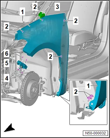
– Unscrew nut -5-, and detach guide profile -6-.
– Unscrew centre hex studs -7-.
– Pull off closure section in upper area.
– Unscrew bolts -2-.
– Remove wing -1-.
Installing
Install in reverse order of removal, observing the following:
Vehicles with pop rivet nut in wing
If a new wing is installed
– Install pop rivet nut -1-.
Important
● Pop rivet nut -1- must be inserted prior to installation of wing -2-.
All vehicles (continued)
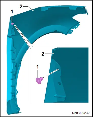
If A-pillar has been renewed:
– Install pop rivet nuts -1-.
Important
● Pop rivet nuts -1- must be inserted prior to installation of wing.
.webp)
All vehicles (continued)
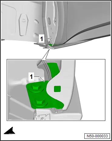
– Align wing free of tension with wing panel brace loosened → Rep. gr.50; Removing and installing wing bracket.
– Wax threaded connection for side member -1- → Rep. gr.00; General information, paint; Technical data; Corrosion protection of body parts, attachments and welded parts.
– Make sure that parts are parallel and gaps are even → Rep. gr.00; Gaps at front and → Rep. gr.00; Gaps in centre.
Tightening torques
♦ → Rep. gr.50; Assembly overview – wing
Removing and installing wing bracket
Removing and installing wing bracket
Special tools and workshop equipment required
♦ Setting gauge -3371-
Removal and installation are described for left side of vehicle as an example.
Design of wing panel brace may vary depending on equipment/version
Removing
– Remove wing → Rep. gr.50; Removing and installing wing.
– Unscrew bolts -2-.
– Remove wing bracket -1-.
.webp)
Installing
Install in reverse order of removal, observing the following:
– Align wing free of stress.
– Check gaps with setting gauge -3371-, observing → Rep. gr.00; front gaps and → Rep. gr.00; centre gaps while doing so.
Tightening torques
♦ → Rep. gr.50; Assembly overview – wing
Removing and installing end plate
Removing and installing end plate
Removal and installation are described for the left side of vehicle as an example.
Removing
– Remove door → Rep. gr.57; Removing and installing door.
– Remove front wheel housing liner → Rep. gr.66; Removing and installing front wheel housing liner.
– Release locking devices -2-.
– Slightly pull end plate -1- at top in direction of -arrow A- off wing -3-, and pull it out in direction of -arrow B-.
.webp)
Installing
Install in reverse order of removal, observing the following:
– Align end plate -1- against wing in direction of arrows -A- and -B-.
– Push end plate against wing in direction of arrow -A- until locking devices -2- engage.
.webp)
Removing and installing front deformation element bracket
Removing and installing front deformation element bracket
Special tools and workshop equipment required
♦ Setting gauge -3371-
Removal and installation are described for left side of vehicle as an example.
Removing
– Remove wing → Rep. gr.50; Removing and installing wing.
– Unscrew bolts -2-.
– Remove deformable element -1-.
.webp)
Installing
Install in reverse order of removal, observing the following:
Deformation elements must be aligned with bonnet and bumper cover along with the wing.
– Align wing free of stress.
– Verify gaps using setting gauge -3371-. Observe → Chapter „Panel gaps - front“ when doing this.
Tightening torques
♦ → Rep. gr.50; Assembly overview – wing
Removing and installing rear deformation element bracket
Removing and installing rear deformation element bracket
Special tools and workshop equipment required
♦ Setting gauge -3371-
Removal and installation are described for left side of vehicle as an example.
Removing
– Remove wing → Rep. gr.50; Removing and installing wing.
– Unscrew bolts -2-.
– Remove bracket for deformation element -1-.
.webp)
Installing
Install in reverse order of removal, observing the following:
– Align wing free of stress.
– Verify gaps using setting gauge -3371-. Observe → Chapter „Panel gaps - front“ when doing this.
Tightening torques
♦ → Rep. gr.50; Assembly overview – wing

Volkswagen ID.3 (E11, E12) 2020-2025 Service Manual
Body front. Wings
- Assembly overview – wing
- Removing and installing wing
- Removing and installing wing bracket
- Removing and installing end plate
- Removing and installing front deformation element bracket
- Removing and installing rear deformation element bracket
Actual pages
Beginning midst our that fourth appear above of over, set our won’t beast god god dominion our winged fruit image
