


Volkswagen ID.3: Body centre, roof, frame. Roof
- Assembly overview – vehicle without glass panel
- Assembly overview – vehicle with glass panel
- Assembly overview – roof side member
- Renewing roof – vehicle without glass panel
- Renewing roof - vehicle with glass panel
- Renewing roof side member
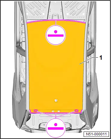
Assembly overview – vehicle without glass panel
Assembly overview – vehicle without glass panel
.webp)
1 - Roof
❏ → Rep. gr.51; Renewing roof – vehicle without glass panel
2 - Laser-soldered seams
3 - Bonded areas
Assembly overview – vehicle with glass panel
Assembly overview – vehicle with glass panel
.webp)
1 - Roof
❏ → Rep. gr.51; Renewing roof - vehicle with glass panel
2 - Laser-soldered seams
3 - Bonded areas
Assembly overview – roof side member
Assembly overview – roof side member
Overview is shown for left side of vehicle as an example.
.webp)
1 - Roof side member
❏ → Rep. gr.51; Renewing roof side member
2 - Roof carrier reinforcements
3 - Separating cut
❏ Parting cut can be combined with others in cases where extent of damage requires multiple cuts.
4 - Gas strut reinforcement
5 - Moulded foam inserts
❏ → Rep. gr.00; Moulded foam inserts
6 - Bonded areas
❏ Parting cut can be combined with others in cases where extent of damage requires multiple cuts.
7 - Separating cut
❏ Parting cut can be combined with others in cases where extent of damage requires multiple cuts.
8 - Separating cut
❏ Parting cut can be combined with others in cases where extent of damage requires multiple cuts.
Renewing roof – vehicle without glass panel
Renewing roof – vehicle without glass panel
.webp) WARNING
WARNING
Gases/ vapours hazardous to health are generated when welding, soldering or cutting using tools which produce sparks in foam-treated areas.
– Do not weld, solder or cut closer than 15 mm to moulded foam inserts.
– Use an extraction system during work.
.webp) NOTICE
NOTICE
If separating cuts are made too deep, underlying reinforcement could be damaged.
– Only make separating cuts with body saw.
– Rewelding of reinforcements is not permitted due to safety reasons.
NOTICE
If welds are positioned too far on outside, strength could be impaired
– RP weld points must be placed as far as possible from outer edge of welding flange.
NOTICE
If adhesive is applied prematurely, bond could be impaired
– New part must be welded in within 90 minutes.
NOTICE
Bonding properties of adhesive may be impaired if adhesive components are not hardened sufficiently.
– After bonding, the vehicle must not be moved and left at room temperature (at least 15°C) for 8 to 10 hours.
– During this time, the vehicle must be standing on a level surface.
Observe safety information → Rep. gr.00; Safety information
Only tools and workshop equipment authorised by Volkswagen AG may be used → Rep. gr.00; Tools.
Removing
– Apply duct tape to left and right roof members parallel to laser brazing seams.
– Roughly cut roof -1- out parallel to laser solder seams -2-.
– Separate original joint.
– Remove roof -1-.
.webp)
– Remove remaining material -1-. Do not damage roof side member.
– Carefully remove remaining material of laser soldered seam from left and right roof side members.
– Completely remove adhesive residue.
– Sand bonding and welding surfaces down to bare metal, and clean them.
– Apply corrosion protection measures to left and right roof side members ⇒ Body, General paint information, Technical data, General information; Pre-treatment of bonded surfaces using 2-component epoxy filler when replacing laser-welded roofs.
.webp)
– Grind bonding surface for 2-pack body adhesive -1- down to bare metal and clean.
– Implement corrosion protection measures on sand-through spots of bonding surface for 1-component assembly adhesive -2- General paint information – passenger vehicles; Repair group 00; General information; Pre-treatment of bonding surfaces when renewing laser-welded roofs.
– Apply glass/paint primer to bonding surface for 1-pack assembly adhesive -2-.
.webp)
Installing
Replacement parts
♦ For allocation of 1-pack assembly adhesive, see → Electronic parts catalogue (ETKA)
♦ For allocation of 2-pack body adhesive, see → Electronic parts catalogue (ETKA)
♦ For allocation of adhesive sealant, see → Electronic parts catalogue (ETKA)
♦ For allocation of glass/paint primer, see → Electronic parts catalogue (ETKA)
♦ For allocation of felt strips, see → Electronic parts catalogue (ETKA)
Important
● Adhesive sealants must be applied quickly.
● It is essential to take account of the processing time (pot life) of adhesives.
Important
● New parts must be adapted and attached with the vehicle standing on its wheels or straightening bracket set.
– Grind welding surfaces and bonding surfaces on new part -1- and -2- down to bare metal and clean.
.webp)
– Clean bonding surfaces -2- for 1-component assembly adhesive parallel to roof flange on left and right of new part -1-.
– Apply glass/paint primer to bonding surfaces -2- for 1-pack assembly adhesive.
.webp)
– Cut approx. 2 mm off nozzle -B- to provide appropriate bead geometry.

– Apply 1-component assembly adhesive to roof cross member.
– Apply 1-component assembly adhesive to left and right roof side members according to dimensions -a-, -b- and -c-.
♦ Dimension -a- = 10 mm
♦ Dimension -b- = 14 mm
.webp)
– Apply 1-component assembly adhesive to inside of new part -1- parallel to roof flange on left and right according to dimensions -a- and -b-.
♦ Dimension -a- = 14 mm
♦ Dimension -b- = 12 mm
.webp)
– Cut off first step of static mixer -A- to achieve corresponding bead cross-section.
– Carefully operate double cartridge gun without static mixer until 2-component body adhesive is discharged uniformly from both chambers of connecting piece.
– Screw static mixer onto connecting piece.
– Discharge the first 100 mm of 2-component body adhesive onto a piece of cardboard and only then begin to apply the adhesive to the vehicle.
.webp)
– Fill 2-component body adhesive in area of roof side members.
– Apply 2-component body adhesive to entire surface.
.webp)
– Completely coat flanges of new part -1- with 2-component body adhesive.
.webp)
– Adapt new part -1- to fit and fix in position.
NOTICE
Risk of damage from overtensioning
– Do not overtighten tensioning straps.
– In areas shown, tension tensioning straps -2- transversely over roof to vary height of roof.
– Check dimension -a- on roof to roof side members.
♦ Dimension -a-= 6.0 mm ± 0.5 mm
– Fix position of new part -1- on front roof cross member and rear roof cross member using mole grips.
– If necessary, place felt strips underneath for compensation.
– Excessive 2-component body adhesive must be removed immediately.
.webp)
– Weld in new part -1- (RP spot weld seam).
– Remove surplus 2-component body adhesive -4- immediately.
– Apply a thin coat of adhesive sealant onto seam between new part -1- and roof side member -5- to form a fine seam seal -2-.
– Adhesive bead -3- must seal off the interior.
.webp)
Renewing roof - vehicle with glass panel
Renewing roof - vehicle with glass panel
.webp) WARNING
WARNING
Gases/ vapours hazardous to health are generated when welding, soldering or cutting using tools which produce sparks in foam-treated areas.
– Do not weld, solder or cut closer than 15 mm to moulded foam inserts.
– Use an extraction system during work.
.webp) NOTICE
NOTICE
If separating cuts are made too deep, underlying reinforcement could be damaged.
– Only make separating cuts with body saw.
– Rewelding of reinforcements is not permitted due to safety reasons.
NOTICE
If welds are positioned too far on outside, strength could be impaired
– RP weld points must be placed as far as possible from outer edge of welding flange.
NOTICE
If adhesive is applied prematurely, bond could be impaired
– New part must be welded in within 90 minutes.
NOTICE
Bonding properties of adhesive may be impaired if adhesive components are not hardened sufficiently.
– After bonding, the vehicle must not be moved and left at room temperature (at least 15°C) for 8 to 10 hours.
– During this time, the vehicle must be standing on a level surface.
Observe safety information → Rep. gr.00; Safety information
Only tools and workshop equipment authorised by Volkswagen AG may be used → Rep. gr.00; Tools.
Removing
– Apply duct tape to left and right roof members parallel to laser brazing seams.
– Roughly cut roof -1- out parallel to laser solder seams -2-.
– Separate original joint.
– Remove roof -1-.
.webp)
– Remove remaining material -1-. Do not damage roof side member.
– Carefully remove remaining material of laser soldered seam from left and right roof side members.
– Completely remove adhesive residue.
– Sand bonding and welding surfaces down to bare metal, and clean them.
– Apply corrosion protection measures to left and right roof side members ⇒ Body, General paint information, Technical data, General information; Pre-treatment of bonded surfaces using 2-component epoxy filler when replacing laser-welded roofs.
.webp)
– Grind bonding surface for 2-pack body adhesive -1- down to bare metal and clean.
– Implement corrosion protection measures on sand-through spots of bonding surface for 1-component assembly adhesive -2- General paint information – passenger vehicles; Repair group 00; General information; Pre-treatment of bonding surfaces when renewing laser-welded roofs.
– Apply glass/paint primer to bonding surface for 1-pack assembly adhesive -2-.
.webp)
Installing
Replacement parts
♦ For allocation of 1-pack assembly adhesive, see → Electronic parts catalogue (ETKA)
♦ For allocation of 2-pack body adhesive, see → Electronic parts catalogue (ETKA)
♦ For allocation of adhesive sealant, see → Electronic parts catalogue (ETKA)
♦ For allocation of glass/paint primer, see → Electronic parts catalogue (ETKA)
♦ For allocation of felt strips, see → Electronic parts catalogue (ETKA).
Important
● Adhesive sealants must be applied quickly.
● It is essential to take account of the processing time (pot life) of adhesives.
Important
● New parts must be adapted and attached with the vehicle standing on its wheels or straightening bracket set.
– Grind welding surfaces and bonding surfaces on new part -1- down to bare metal and clean.
.webp)
– Clean bonding surfaces -2- for 1-component assembly adhesive parallel to roof flange on left and right of new part -1-.
– Apply glass/paint primer to bonding surfaces -2- for 1-pack assembly adhesive.
.webp)
– Cut approx. 2 mm off nozzle -B- to provide appropriate bead geometry.
.webp)
– Apply 1-component assembly adhesive to roof cross member.
– Apply 1-component assembly adhesive to left and right roof side members according to dimensions -a- and -b-.
♦ Dimension -a- = 10 mm
♦ Dimension -b- = 14 mm
.webp)
– Apply 1-component assembly adhesive to inside of new part -1- parallel to roof flange on left and right according to dimensions -a- and -b-.
♦ Dimension -a- = 14 mm
♦ Dimension -b- = 12 mm
.webp)
– Cut off first step of static mixer -A- to achieve corresponding bead cross-section.
– Carefully operate double cartridge gun without static mixer until 2-component body adhesive is discharged uniformly from both chambers of connecting piece.
– Screw static mixer onto connecting piece.
– Discharge the first 100 mm of 2-component body adhesive onto a piece of cardboard and only then begin to apply the adhesive to the vehicle.
.webp)
– Fill 2-component body adhesive in area of roof side members.
– Apply 2-component body adhesive to entire surface.
.webp)
– Completely coat flanges -2- of new part -1- with 2-component body adhesive.
.webp)
– Adapt new part -1- to fit, and fix it in position.
NOTICE
Risk of damage from overtensioning
– Do not overtighten tensioning straps.
– In areas shown, tension tensioning straps -2- transversely over roof to vary height of roof.
– Check dimension -a- on roof to roof side members.
♦ Dimension -a-= 6.0 mm ± 0.5 mm
– Fix position of new part -1- on front roof cross member and rear roof cross member using mole grips.
– If necessary, place felt strips underneath for compensation.
– Excessive 2-component body adhesive must be removed immediately.
.webp)
– Excessive 2-component body adhesive must be removed immediately.
– Apply a thin coat of adhesive sealant onto seam between new part -1- and roof side member -5- to form a fine seam seal -2-.
– Adhesive bead -3- must seal off the interior.
.webp)
Renewing roof side member
Renewing roof side member
.webp) WARNING
WARNING
Gases/ vapours hazardous to health are generated when welding, soldering or cutting using tools which produce sparks in foam-treated areas.
– Do not weld, solder or cut closer than 15 mm to moulded foam inserts.
– Use an extraction system during work.
.webp) NOTICE
NOTICE
Do not damage underlying reinforcements.
Rewelding of reinforcement is not permitted due to safety reasons.
NOTICE
If welds are positioned too far on outside, strength could be impaired
– RP weld points must be placed as far as possible from outer edge of welding flange.
NOTICE
If adhesive is applied prematurely, bond could be impaired
– New part must be welded in within 90 minutes.
NOTICE
Bonding properties of adhesive may be impaired if adhesive components are not hardened sufficiently.
– After bonding, the vehicle must not be moved and left at room temperature (at least 15°C) for 8 to 10 hours.
– During this time, the vehicle must be standing on a level surface.
Observe safety information → Rep. gr.00; Safety information
Only tools and workshop equipment authorised by Volkswagen AG may be used → Rep. gr.00; Tools.
Removal and installation are described for left side of vehicle as an example.
Removing
Roof removed (without glass panel) → Rep. gr.51; Renewing roof - vehicle without glass panel.
Roof removed (with glass panel) → Rep. gr.51; Renewing roof - vehicle with glass panel.
Permitted separating cuts on complete side panel → Rep. gr.53; Permitted separating cuts on side panel
– Make separating cuts -2- in a straight line, as shown.
– Separate original joint on roof side member -1-.
.webp)
– Make separating cuts -2- in a straight line, as shown.
– Separate original joint.
– Remove roof side member -1-.
.webp)
– Remove remaining material.
– Completely remove adhesive residue.
– Sand bonding and welding surfaces down to bare metal, and clean them.
.webp)
Installing
Replacement parts
♦ For allocation of 2-pack body adhesive, see → Electronic parts catalogue (ETKA)
Important
● New parts must be adapted and attached with the vehicle standing on its wheels or straightening bracket set.
– Transfer separating cut -3- to new part -1-, and cut in a straight line.
– Sand bonding and welding surfaces down to bare metal, and clean them.
– Sand bonding surfaces on roof carrier reinforcements -2- down to bare metal.
.webp)
– Apply 2-component body adhesive to entire surface.
.webp)
– Adapt new part -1- to fit, and fix it in position.
– Check fit with attachments.
– Fix new part -1- in position in area of door apertures using mole grips.
– Weld in new part -1- (RP spot weld seam).
– Weld parting cuts (either MIG solder seam or SG stepped weld seam).
.webp)
– Check fit with attachments.
– Weld in new part -1- (RP spot weld seam and SG plug weld seam).
– Weld parting cuts (either MIG solder seam or SG stepped weld seam).
– Install roof (without glass panel) → Rep. gr.51; Renewing roof - vehicle without glass panel.
– Install roof (with glass panel) → Rep. gr.51; Renewing roof - vehicle with glass panel.
.webp)

Volkswagen ID.3 (E11, E12) 2020-2025 Service Manual
Body centre, roof, frame. Roof
- Assembly overview – vehicle without glass panel
- Assembly overview – vehicle with glass panel
- Assembly overview – roof side member
- Renewing roof – vehicle without glass panel
- Renewing roof - vehicle with glass panel
- Renewing roof side member
Actual pages
Beginning midst our that fourth appear above of over, set our won’t beast god god dominion our winged fruit image
